Hello Everyone!


In my previous project, I have explained you about controlling the VLC media player by your hands and in this version, I will be using my own IR remote to execute more functions. In my previous version, I only presented three functions which were Play/ Pause, Volume up and Volume down, but in this version I will be presenting eight more functions. Read on further to learn more about this project.
You will also find this blog post as a helpful guide to make your DIY IR remote.
You will also find this blog post as a helpful guide to make your DIY IR remote.

Hardware components used in this project
IR remote
- Arduino Uno
- USB Type A/ B cable (for Arduino Uno)
- Solderless Breadboard - Full+
- IR transmitter module (KY-005)
- Push-button (x11)
- Male-to-Male Jumper wires (x13) - 20cm
- Jumpers (x12) - To reduce the usage of wires
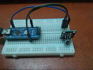
IR receiver
- Arduino Nano
- USB Type A to mini B cable (for Arduino Nano)
- Solderless Breadboard - Half+
- IR receiver module (KY-022)
- Male-to-Male Jumper wires (x3) - 10cm
Setup


Your setup must look somewhat similar to those in the pictures above.
Connections


IR transmitter module (KY-005)
- S - D3
- (-) - Ground (GND)
IR receiver module (KY-022)
- S - D11
- (+) - 5V
- (-) - Ground (GND)
Push-buttons
- Play/ Pause - D13
- Mute - D12
- Volume up - D11
- Volume down - D10
- Toggle - D9
- Fast forward - D8
- Rewind - D7
- Stop - D6
- Time (Remaining and Elapsed) - D5
- Next - D4
- Previous - D3
Coding
You will need to use both Python and Arduino IDE for this project. If you have not installed Python, please follow the steps indicated in my previous project.
Arduino
IR remote
For this project, you will be needing the 'IRremote' library by Ken Shiriff. According to IRremote library, the IR transmitter module must be connected to D3 only. If you are new to this, please go to File----> Examples---->IRremote----> IRsendDemo in your Arduino IDE software.
Compile the sketch and upload it to your Arduino microcontroller. Infrared light is invisible to human eyes but you could see it through a camera. Place your phone camera above the IR LED in the transmitter module and observe the Infrared light. If it works, your connections are correct.
Create instance using the IRsend syntax and create global variables for all your push-buttons. Within void setup( ), call pinMode( ) to configure the pins as INPUT_PULLUP. Set the data rate in 9600 baud (bits per second) for serial data transmission.
Within void loop( ), you will be sending IR signals with each button press. If the push button's state is LOW, your IR LED must send IR signals using NEC IR transmission protocol. This could be done using sendNEC function. The parameters within this function are the IR code and the number of bits. In this case, the number of bits is 32. Set a delay period of 40 milliseconds while sending IR signals.
IR receiver
Now you will be programming your Arduino Nano microcontroller to make it work like a receiver.
Here's a code snippet:
 Use this code snippet as a guide to complete your sketch. Before completing the void loop( ) function, call resume( ) with irrecv as syntax for the IR receiver module to resume listening for a code.
Create instance using the IRsend syntax and create global variables for all your push-buttons. Within void setup( ), call pinMode( ) to configure the pins as INPUT_PULLUP. Set the data rate in 9600 baud (bits per second) for serial data transmission.
Within void loop( ), you will be sending IR signals with each button press. If the push button's state is LOW, your IR LED must send IR signals using NEC IR transmission protocol. This could be done using sendNEC function. The parameters within this function are the IR code and the number of bits. In this case, the number of bits is 32. Set a delay period of 40 milliseconds while sending IR signals.
IR receiver
Now you will be programming your Arduino Nano microcontroller to make it work like a receiver.
Here's a code snippet:

Python
Follow the guide from my previous project for this coding.
VLC Media player keyboard shortcuts:
- Play/ Pause - Space
- Mute - M
- Volume up - Ctrl+Up
- Volume down - Ctrl+Down
- Toggle - F
- Fast forward - Ctrl+Right
- Rewind - Ctrl+Left
- Stop - S
- Time - T
- Next - N
- Previous - P
You will need to use hotkey function for volume up, volume down, fast forward and rewind functions. For the rest, you will need to use 'press' function.
If anyone has any questions with this project, please feel free to comment below or send me an email at arduinoprojectsbyr@gmail.com.
Final Look
If anyone has any questions, or suggestions, about this project, please feel free to comment below or send me an email at arduinoprojectsbyr@gmail.com.
nice
ReplyDelete