
55. IoT Home automation using Google Home Mini and Arduino

Hello everyone!
In my last post, I had discussed about my reassembled relay module and today I will be explaining you about my IoT Home automation using Google Home Mini and Arduino. You will be needing the Blynk and IFTTT apps for this project.

Hardware components used in this project

  • NodeMCU DEVKIT 1.0
  • Google Home Mini
  • Breadboard power supply module - 3.3V/ 5V
  • Solderless Breadboard - Half +
  • Relay module (x4) - 5V single channel
  • 5V DC mini water pump - Submersible
  • Solenoid door lock - 12V DC
  • RGB LED - Common anode
  • Resistors (x3) - 220Ω
  • Male-to-Male Jumper wires
  • Female-to-Male Jumper wires
  • Plug extension
  • Voltage regulator/ 12V DC power adapter

Apps used in this project

  • Arduino IDE
  • Blynk App
  • If This Then That App - IFTTT

Tools used in this project

  • Standard Screwdriver (aka Flat head screwdriver)
  • Soldering iron
  • Solder

Setup


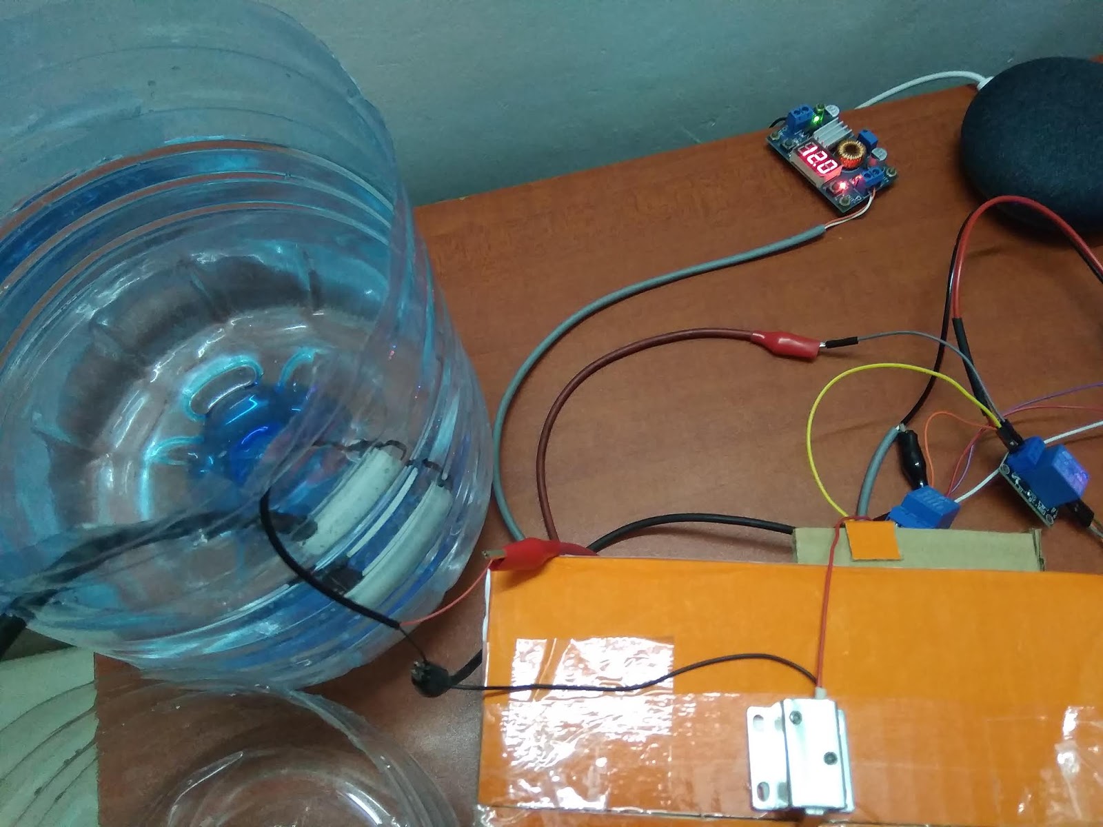
Your setup must look somewhat similar to those in the pictures above.

Connections

Relay module - 5V single channel

  • (+) - 5V
  • (-) - Ground (GND)
  • S (Pedestal Fan) - D1
  • S (Soldering station) - D2
  • S (Water pump) - D3
  • S (Solenoid door lock) - D4

RGB LED - common anode 

  • Red - D5
  • Green - D6
  • Red - D7
  • (+) - 5V

Coding

For this project, you will be needing the Blynk and IFTTT app. To get started with Blynk, please visit this link:
Use the example code builder to choose your hardware model and connectivity type, and copy the whole code to buffer.
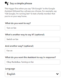
Upload this code to your Microcontroller board and connect your board with Blynk app. Visit ifttt.com to get started with IFTTT. Create applets using Google Assistant and Webhooks services. Make sure that you use the same gmail address for the IFTTT account and your Google Assistant/ Google Home Mini.
Here is an example of my applet used to switch on the fan:
If anyone has any questions with the coding, please feel free to comment below or send me an email at arduinoprojectsbyr@gmail.com.

Final Look

If anyone has any questions, or suggestions, with this project, please feel free to comment below or send me an email at arduinoprojectsbyr@gmail.com.

Comments

  1. This is a nice work. I gonna test this. Great work 💪

    ReplyDelete
  2. Looks awesome. I assume it would be similar for Amazon Alexa?

    ReplyDelete

Post a Comment

Popular posts from this blog

51. Buzz wire game using Arduino

Hello everyone! This is my first Arduino project in 2020 and it is going to be a fun and simple project. You would have heard of the Buzz Wire, a steady hand game, and today you will be learning to make one using Arduino. Hardware components used in this project Arduino Nano USB Type A to mini B cable (for Arduino Nano) Solderless Breadboard - Mini and Full-size LEDs (x2) - Green and Red Resistors (x2) - 220 Ω  Active Buzzer module (KY-012) LCD display module with I2C interface - 16x2 Male-to-Male Jumper wires (x4) - 10cm Female-to-Male Jumper wires (x5) - 20 cm Jumpers (x5) - to reduce the usage of wires Copper wire  Tape (or any form of insulation)  Setup Your hardware setup must look somewhat similar to the ones in the images above. The beginning and end of the copper wire maze must be taped to prevent conductivity between the wire loop and maze. Connections LCD display module with I2C interface GND - Ground VCC - 5V SDA - A4 SCL - A5

71. Buzz Wire Game ( Version 2.0 ) using Arduino

Hey Everyone! I hope that everyone's safe during this pandemic. Today I am going to explain you about the second version of my Buzz wire game. People who are bored of staying indoors can find this game pretty interesting and fun to play.  If you are a beginner, you can start off with my first version of this project :  51. Buzz wire game using Arduino   Hardware components used in this project Arduino Uno Solderless Breadboard (x2) - Full/ Full+ LCD display module with I2C module - 16x2 Potentiometer - B20K Push-buttons (x3) Resistor - 220 Ω Active Buzzer module (KY-012) LED - Red Copper Wire - 19/ 20 gauge thick Male-to-Male Jumper wires - 10cm and 20cm Wire - Long enough to connect the loop of copper wire to ground Other tools required for this project Cutting pliers - To cut the right amount of copper wire Round-nose pliers - To bend the copper wire and make a maze and loop Hardware setup Connections Wire Maze - D2 Wire loop - Ground (GND) B20K Potentiometer S - A0 (+) - 5V (-)

86. RFID Health tag (Arduino and Python)

 Hey everyone, Sorry I have not uploaded in a while. Today, I will be sharing an interesting project with all of you. This RFID Health tag project is useful when it comes to keeping track of vaccinated individuals, their biodata and their health conditions and medications. For this project, you will be needing Arduino and Python. Read on further to see how I did this project. Hardware components used in this project Arduino Uno Solderless Breadboard - Half+ MRFC522 RFID reader RFID key tags (x5) Push-buttons (x2) Male-to-Male Jumper wires (x12) USB Type A/ B cable (for Arduino Uno) Software required Arduino IDE - latest version recommended Python 3.8 Schematic MFRC522 RFID reader SDA/ SS - D10 SCK - D13 MOSI - D11 MISO - D12 IRQ - Not connected GND - Ground RST/ RESET - D9 3.3V - 3.3V Push-buttons Submit button - D4 Retrieve button - D5 Coding Arduino For this project, you will be using the following libraries: MFRC522 by miguelbalboa -  https://github.com/miguelbalboa/rfid SPI - In-bu