Hey everyone!
I am back with an interesting project. Today, you will be learning about controlling a Simple 2 axis Robotic Arm, made from Micro servo motors, with an MPU-6050 sensor module. Please feel free to visit my previous blog post to learn about the MPU-6050 sensor module.

Hardware components used in this project
- Arduino Mega 2560 - You could use any other Arduino microcontroller, but make sure you use an external power supply.
- USB Type A/B cable (for Arduino Mega 2560)
- MPU-6050 sensor module
- SG-90 Tower Pro Micro Servo motor (x2)
- Male-to-Male Jumper wires (x6)
- Male-to-Female Jumper wires (x5)
Setup


Schematic
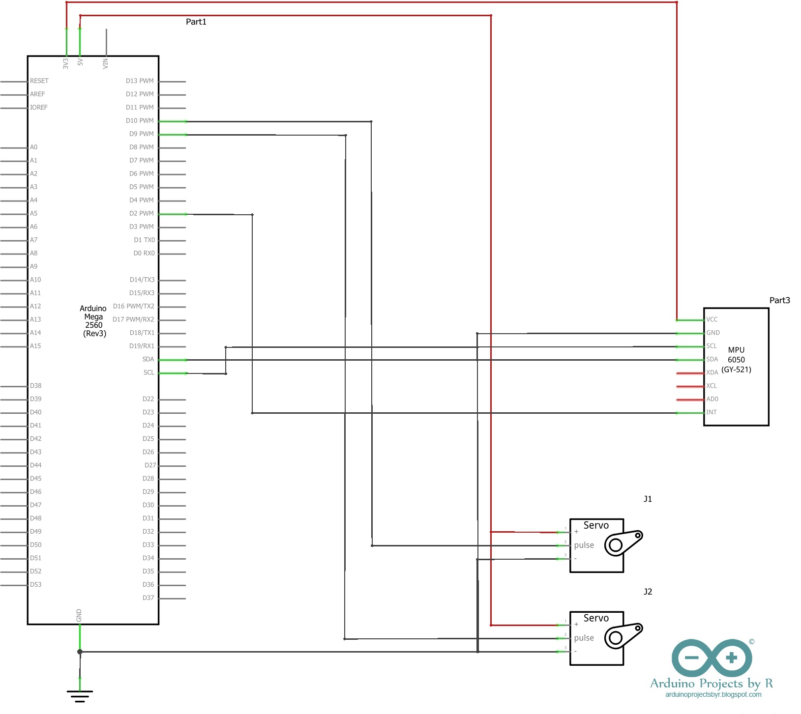
MPU-6050 sensor module
- VCC - 3.3V
- GND - Ground
- SDA - D20 (Arduino Mega 2560), A4 (Arduino Uno and Nano)
- SCL - D21 (Arduino Mega 2560), A5 (Arduino Uno and Nano)
- INT - D2
Micro servo motor (Roll)
- S (Yellow/ Orange) - D9
- + (Red) - 5V
- - (Black/ Brown) - GND
Micro servo motor (Pitch)
- S (Yellow/ Orange) - D10
- + (Red) - 5V
- - (Black/ Brown) - GND

Coding
As I already mentioned in my previous blog post, you will be needing Jeff Rowberg's I2C Development library and the MPU-6050 library to interface your MPU-6050 sensor module with the Arduino microcontroller board. To learn more about the libraries, please visit Jeff's website.
Go to File menu from the top menu bar and select the MPU6050_DMP6 example sketch from the MPU6050 library. Upload it to your Arduino microcontroller board and observe the readings produced by the sensor module. Rotate the sensor module to notice the changes and identify the roll, pitch and yaw. Roll (longitudinal axis), pitch (transverse axis) and yaw (vertical axis) are aircraft principal axes.
For this project, we will be using only the roll and pitch measurements to control the simple robotic arm. The robotic arm is made using two micro servo motors so you will be needing the Servo library for your microcontroller to control the servo motor movement.
Use attach( ) function to declare the pins to which your servo motors are attached and set the initial position of your servo motors as zero within void setup( ). If you read the codes carefully, you would notice that the Roll measurements (in degrees) are indicated as ypr[2] * 180/M_PI.
Rotate the sensor module and observe the measurements produced to calculate the offsets and the range. Finally, you should use this range to map the measurements to the servo motor's position. Watch the YouTube video in the final section to understand how this works.
If anyone has any questions about the codes, please feel free to comment below. Please do not send me any email requesting the complete codes.
Final Look
If anyone has any questions or suggestions about this project, please let me know in the comment section below or send me an email at arduinoprojectsbyr@gmail.com.
Comments
Post a Comment