
49. IoT - First step towards Home automation

Hey everyone!
Today I am going to teach you about Internet of Things (IoT). This is my first IoT project and the first step towards home automation. Using IoT, interrelated computing devices are able to transfer data over a network without requiring human-to-human or human-to-computer interaction. In this page, you will see how I controlled my pedestal fan and soldering station with my smartphone.
To learn about IoT, click here.

Hardware components used in this project

  • Arduino Uno
  • Ethernet Shield W5100
  • Relay module (x2) - 5V single channel
  • Female-to-Male Jumper wires (x3) - 20cm
  • Male-to-Male Jumper wires (x3) - 70cm
  • Male header pins - 3 pins
  • Female header pins - 3 pins
  • Plug extension
  • Wire (x2) - 10 cm
  • Ethernet cable
  • Wifi router
  • Smartphone/ Tablet

Software apps

  • Arduino IDE
  • Blynk app 

Setup


Your setup must look somewhat similar to those in the pictures above.

Connections

Relay module 01 (Soldering station) - 5V single channel

  • S - D2
  • (+) - 5V
  • (-) - Ground (GND)

Relay module 02 (Fan) - 5V single channel

  • S - D3
  • (+) - 5V
  • (-) - Ground (GND)

Coding

You will be needing Blynk app for this IoT project. If you are new to Blynk, please feel free to follow the hyperlink. If your smartphone or tablet uses the Android OS, you can install Blynk app in playstore. Blynk app only works in iOS and android.  Follow the steps given in this page (https://blynk.io/en/getting-started) to successfully work with Blynk.
Open Example Code Builder, choose your hardware model and connection type. Within Examples, choose Blynk Blink option and copy the whole code to buffer. Add your Auth Token in the codes. The Auth token will be sent to your email address. Upload the code to your Arduino Uno.
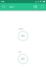
Open Blynk App and tap PLAY. Wait till you see the message that your device is connected and online.
Now, you can control the electronic devices which you connect to the plug extension.
Happy Blynking!
If anyone has any questions with the coding, please feel free to comment below or send me an email at arduinoprojectsbyr@gmail.com.

Final Look

If anyone has any questions, or suggestions, about this project, please don't hesitate to comment below or send me an email at arduinoprojectsbyr@gmail.com.


Comments

Popular posts from this blog

77. Controlling Micro servo Robotic Arm with MPU-6050 sensor module

 Hey everyone! I am back with an interesting project. Today, you will be learning about controlling a Simple 2 axis Robotic Arm, made from Micro servo motors, with an MPU-6050 sensor module. Please feel free to visit my previous blog post to learn about the MPU-6050 sensor module. Hardware components used in this project Arduino Mega 2560 - You could use any other Arduino microcontroller, but make sure you use an external power supply. USB Type A/B cable (for Arduino Mega 2560) MPU-6050 sensor module SG-90 Tower Pro Micro Servo motor (x2) Male-to-Male Jumper wires (x6) Male-to-Female Jumper wires (x5) Setup Schematic MPU-6050 sensor module VCC - 3.3V GND - Ground SDA - D20 (Arduino Mega 2560), A4 (Arduino Uno and Nano) SCL - D21 (Arduino Mega 2560), A5 (Arduino Uno and Nano) INT - D2 Micro servo motor (Roll) S (Yellow/ Orange) - D9 + (Red) - 5V - (Black/ Brown) - GND  Micro servo motor (Pitch) S (Yellow/ Orange) - D10 + (Red) - 5V - (Black/ Brown) - GND Coding As I alread...

85. Analog and Digital Clock on Adafruit TFT Display using Arduino

 Hey everyone, Sorry I have not posted in a while. Today, I will be presenting you my Analog and Digital Clock on Adafruit TFT Display using Arduino. You can find the schematic and code explanation within this post. Read on further to learn how I did this project. Hardware components used in this project Arduino Mega 2560 Adafruit 2.8" TFT Touch Shield for Arduino w/ Capacitive Touch - You could also use any other Arduino compatible TFT display DS1307 RTC Module Solderless Breadboard - Half+ (This is optional if you are connecting the RTC module to the development board directly) Jumper wires (x4) - Male/Male jumper wires if using solderless breadboard. Female/Male if connecting RTC module directly to Arduino Mega. Software apps Arduino IDE - latest version is recommended Setup Connections DS1307 RTC Module SCL - A5 SDA - A4 VCC - 5V GND - Ground Adafruit TFT Touch shield You can simply place the Adafruit TFT Touch shield onto your Arduino Mega 2560 development board. Make sure to...

57. Using Blynk with Arduino Uno and ESP8266 WiFi module

Hello Everyone! Today I am going to explain you how to connect your Arduino Uno with Blynk using the ESP8266 WiFi module. I have already demonstrated you about connecting your Arduino Uno with Blynk app using the Ethernet Shield W5100 and this will be the second version of that project .  Hardware components used in this project Arduino Uno ESP-01 ESP8266 WiFi module USB to TTL converter Solderless Breadboard - Half+ Breadboard power supply module - 3.3V/ 5V RGB LEDs (x3) - Common Anode Resistors (x3) - 220 Ω Relay module - 5V single channel Male-to-Male Jumper wires Female-to-Male Jumper wires Setup Your setup must look somewhat similar to that shown in the images above. Connections ESP8266 ESP-01 wifi module GND - Ground GPIO0- Not connected GPIO2 - Not connected RXD - D2 TXD - D3 CH_PD - VCC - 3.3V RESET - Not connected VCC - 3.3V  *Note: Do not connect your ESP8266 ESP-01 wifi module with 5V. RGB LED - Common Anode Anode -...