
18. Prototype - Touch activated Light bulb

In this project, you will learn how to switch on a light bulb with just a touch. We will be using a Human Touch sensor (KY-036) and if you don't know how it works, feel free to look up the previous project.

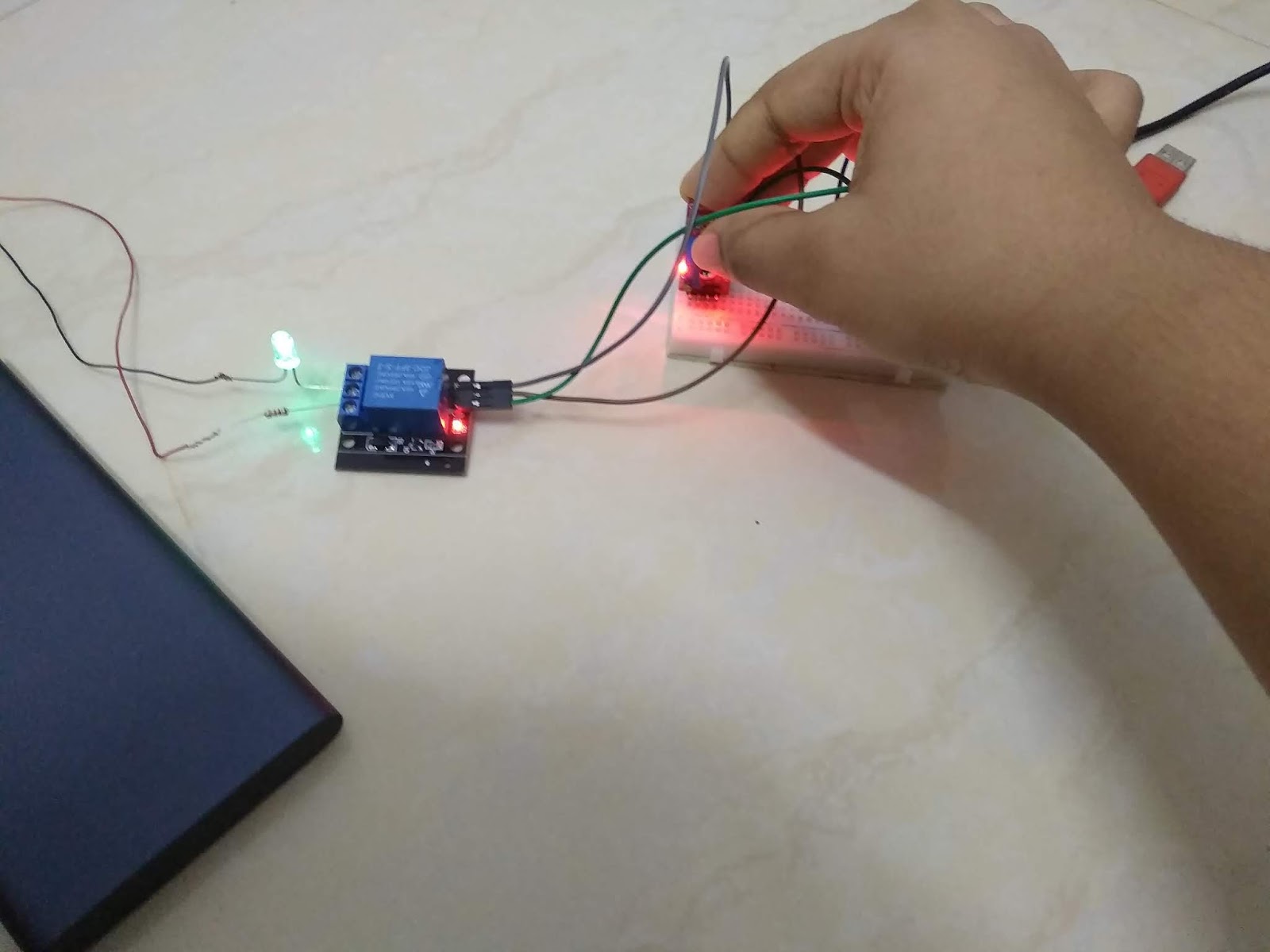
*Precaution: Ensure safety when working with mains electricity. For beginners, I would recommend connecting the LED and 1kΩ resistor to the relay module as a prototype. The LED and power bank will substitute the lamp and the mains electricity respectively.

Supplies

  • Arduino Nano
  • Solderless Breadboard - Mini
  • Human Touch sensor (KY-036)
  • Relay Module
  • LED (any colour)
  • 1kΩ resistor
  • Male-to-male jumper wires (10cm)
  • Female-to-male jumper wires (20cm)
  • Power bank - 10000 mAh
  • USB 2.0 Type A to Mini B cable (For Arduino Nano)
  • USB 2.0 Type A cable (For power bank)

Setup 


For more information about the setup, please watch the YouTube video posted at the bottom of this page.

Connections


  • Relay Module - D5
  • Human Touch sensor - D3
  • (+) of Human Touch sensor - 5V
  • (-) of Human Touch sensor - GND

Coding

Final Look


If anyone has any suggestions or complaints about this project, please feel free to comment below or email me at arduinoprojectsbyr@gmail.com


Comments

  1. How am I supposed to copy the code? its a freakin image...

    ReplyDelete
    Replies
    1. You are not supposed to copy it. You should study and understand the codes before you implement them.

      Delete

Post a Comment

Popular posts from this blog

51. Buzz wire game using Arduino

Hello everyone! This is my first Arduino project in 2020 and it is going to be a fun and simple project. You would have heard of the Buzz Wire, a steady hand game, and today you will be learning to make one using Arduino. Hardware components used in this project Arduino Nano USB Type A to mini B cable (for Arduino Nano) Solderless Breadboard - Mini and Full-size LEDs (x2) - Green and Red Resistors (x2) - 220 Ω  Active Buzzer module (KY-012) LCD display module with I2C interface - 16x2 Male-to-Male Jumper wires (x4) - 10cm Female-to-Male Jumper wires (x5) - 20 cm Jumpers (x5) - to reduce the usage of wires Copper wire  Tape (or any form of insulation)  Setup Your hardware setup must look somewhat similar to the ones in the images above. The beginning and end of the copper wire maze must be taped to prevent conductivity between the wire loop and maze. Connections LCD display module with I2C interface GND - Ground VCC - 5V SDA -...

70. Arduino Stopwatch and Timer

Hello everyone! Today I am going to explain you about making an Arduino Stopwatch and Timer, which can be used for time based projects. Read on further to learn more about this project. Hardware components used in this project Arduino Uno USB Type A/ B cable Solderless Breadboard - Full+ LCD display module with I2C interface - 16x2 Potentiometer - 10K Push-buttons (x5) Active Buzzer module (KY-012) LED - Red Resistors (x6) - 10kΩ (x5) and 220Ω (x1) Male-to-Male Jumper wires - 10cm and 20cm Jumpers - to reduce the usage of wires Hardware setup Connections 10K Potentiometer S - A0 (+) - 5V (-) - Ground (GND) Active Buzzer module S - D7 (+) - 5V (-) - Ground (GND) 16x2 LCD display module with I2C interface GND - Ground VCC - 5V SDA - A4 SCL - A5 Push-buttons (+) - 5V (-) - Ground (GND) S - D2, D3, D4, D5, D6 Coding Now, I will explain you about how this real-time project works and you can figure out the coding by this idea.  Push-buttons and their functions D2 - Set Countdown timer D3...

71. Buzz Wire Game ( Version 2.0 ) using Arduino

Hey Everyone! I hope that everyone's safe during this pandemic. Today I am going to explain you about the second version of my Buzz wire game. People who are bored of staying indoors can find this game pretty interesting and fun to play.  If you are a beginner, you can start off with my first version of this project :  51. Buzz wire game using Arduino   Hardware components used in this project Arduino Uno Solderless Breadboard (x2) - Full/ Full+ LCD display module with I2C module - 16x2 Potentiometer - B20K Push-buttons (x3) Resistor - 220 Ω Active Buzzer module (KY-012) LED - Red Copper Wire - 19/ 20 gauge thick Male-to-Male Jumper wires - 10cm and 20cm Wire - Long enough to connect the loop of copper wire to ground Other tools required for this project Cutting pliers - To cut the right amount of copper wire Round-nose pliers - To bend the copper wire and make a maze and loop Hardware setup Connections Wire Maze - D2 Wire loop - Ground (GND) B20K Potentiometer S - A0 (+)...