
04. Controlling an LED using a Push-button

Push-button is an example of mechanical switch. When it is pressed, the circuit is complete and when released, there is a gap in the circuit.

Supplies:

  • LED
  • Push-button
  • Resistors - 220Ω and 10kΩ
  • Arduino Uno R3
  • Solderless Breadboard - Mini
  • Jumper Wires

Setting up your hardware
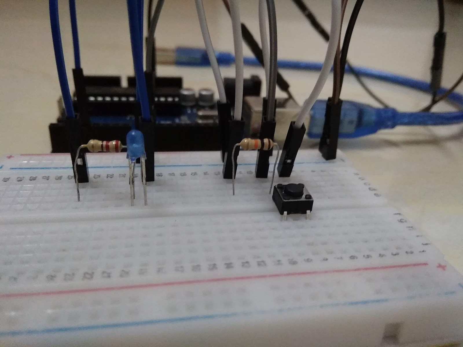


Connections:

  • Cathode (LED) ---> GND
  • Anode (LED) ---> D3
  • Push-button ---> D9

Coding

These codes will make the LED light up when the push-button is pressed and off when the button is released.
Compile your sketch and upload it to your Arduino Board after connecting it to your computer.

Final look

If you have any questions, please feel free to comment them below or send an email to arduinoprojectsbyr@gmail.com.

Comments

Popular posts from this blog

77. Controlling Micro servo Robotic Arm with MPU-6050 sensor module

 Hey everyone! I am back with an interesting project. Today, you will be learning about controlling a Simple 2 axis Robotic Arm, made from Micro servo motors, with an MPU-6050 sensor module. Please feel free to visit my previous blog post to learn about the MPU-6050 sensor module. Hardware components used in this project Arduino Mega 2560 - You could use any other Arduino microcontroller, but make sure you use an external power supply. USB Type A/B cable (for Arduino Mega 2560) MPU-6050 sensor module SG-90 Tower Pro Micro Servo motor (x2) Male-to-Male Jumper wires (x6) Male-to-Female Jumper wires (x5) Setup Schematic MPU-6050 sensor module VCC - 3.3V GND - Ground SDA - D20 (Arduino Mega 2560), A4 (Arduino Uno and Nano) SCL - D21 (Arduino Mega 2560), A5 (Arduino Uno and Nano) INT - D2 Micro servo motor (Roll) S (Yellow/ Orange) - D9 + (Red) - 5V - (Black/ Brown) - GND  Micro servo motor (Pitch) S (Yellow/ Orange) - D10 + (Red) - 5V - (Black/ Brown) - GND Coding As I alread...

57. Using Blynk with Arduino Uno and ESP8266 WiFi module

Hello Everyone! Today I am going to explain you how to connect your Arduino Uno with Blynk using the ESP8266 WiFi module. I have already demonstrated you about connecting your Arduino Uno with Blynk app using the Ethernet Shield W5100 and this will be the second version of that project .  Hardware components used in this project Arduino Uno ESP-01 ESP8266 WiFi module USB to TTL converter Solderless Breadboard - Half+ Breadboard power supply module - 3.3V/ 5V RGB LEDs (x3) - Common Anode Resistors (x3) - 220 Ω Relay module - 5V single channel Male-to-Male Jumper wires Female-to-Male Jumper wires Setup Your setup must look somewhat similar to that shown in the images above. Connections ESP8266 ESP-01 wifi module GND - Ground GPIO0- Not connected GPIO2 - Not connected RXD - D2 TXD - D3 CH_PD - VCC - 3.3V RESET - Not connected VCC - 3.3V  *Note: Do not connect your ESP8266 ESP-01 wifi module with 5V. RGB LED - Common Anode Anode -...

70. Arduino Stopwatch and Timer

Hello everyone! Today I am going to explain you about making an Arduino Stopwatch and Timer, which can be used for time based projects. Read on further to learn more about this project. Hardware components used in this project Arduino Uno USB Type A/ B cable Solderless Breadboard - Full+ LCD display module with I2C interface - 16x2 Potentiometer - 10K Push-buttons (x5) Active Buzzer module (KY-012) LED - Red Resistors (x6) - 10kΩ (x5) and 220Ω (x1) Male-to-Male Jumper wires - 10cm and 20cm Jumpers - to reduce the usage of wires Hardware setup Connections 10K Potentiometer S - A0 (+) - 5V (-) - Ground (GND) Active Buzzer module S - D7 (+) - 5V (-) - Ground (GND) 16x2 LCD display module with I2C interface GND - Ground VCC - 5V SDA - A4 SCL - A5 Push-buttons (+) - 5V (-) - Ground (GND) S - D2, D3, D4, D5, D6 Coding Now, I will explain you about how this real-time project works and you can figure out the coding by this idea.  Push-buttons and their functions D2 - Set Countdown timer D3...