
59. Arduino Light Tracker V2.0

Hello everyone!
Today I am going to explain you about making the second version of my light tracker. This light tracker will move in both horizontal and vertical directions. You can read about the first version of the light tracker here

Hardware components used in this project

  • Arduino Uno
  • USB Type A/ B cable (for Arduino Uno)
  • Solderless Breadboard - Full+
  • Breadboard Power supply module - 3.3/ 5 V
  • Towerpro Micro servo motor (x2) - SG90
  • Photoresistor (x4) - also known as LDR
  • Resistors (x4) - 1kΩ
  • Male-to-Male Jumper wires

Tools and other supplies 

  • Soldering station/ iron
  • Solder
  • Double sided tape
  • 3D printed/ cardboard bracket

Setup


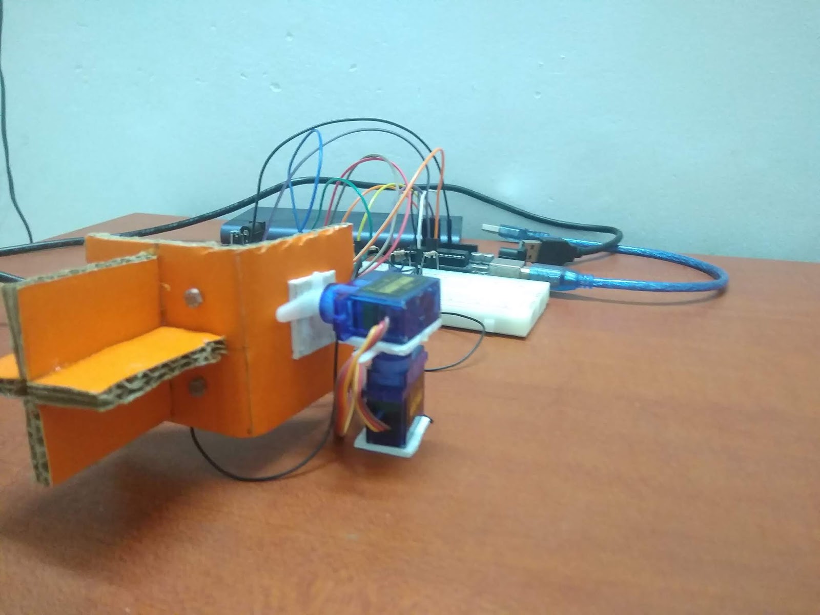
Your setup must look somewhat similar to those in the pictures above.

Connections

TowerPro Micro servo motor - SG90

  • (+) (Red wire) - 5V
  • (-) (Black/ Brown wire) - Ground (GND)
  • S (Yellow/ Orange wire) - D9 [Vertical movement]
  • S (Yellow/ Orange wire) - D10 [Horizontal movement]

Photoresistor

  • Bottom right - A0
  • Top right - A1
  • Bottom left - A2
  • Top left - A3

Coding

For this project, you will be needing the 'Servo' library by Michael Margolis. If you are new to using this library, feel free to follow this link: https://www.arduino.cc/en/reference/servo.
Include the library in your sketch and create servo objects by using servo syntax. Create global variables for your LDRs. 
Within void setup( ), use attach( ) function to declare the pin to which the servos are attached and set the initial position of the servos as 90 by using write( ) function. You do not have to use the pinMode() function to configure the pins of the LDR as INPUT because they are already connected to the Analog ports.
Within void loop( ), create local variables to read the analog values produced by the LDRs. Calculate the average values and store them in variables named 'top', 'bottom', 'left' and 'right'.
  • top = (topright+topleft)/2
  • bottom = (bottomright+bottomright)/2
  • right=(topright+bottomright)/2
  • left=(topleft+bottomleft)/2
If the value stored in the top variable is greater than that stored in the bottom variable, the vertical servo's position must increment by one. If it is the opposite, then the position must decrement by one.
If the value stored in the right variable is greater than that stored in the left variable, the horizontal servo's position must increment by one. If it is the opposite, then the position must decrement by one. 
Set a delay period of 100 milliseconds before completing the loop.
If anyone has any questions with the coding, please feel free to comment below or send me an email at arduinoprojectsbyr@gmail.com.

Final Look

If anyone has any questions, or suggestions, about this project, please feel free to comment below or send me an email at arduinoprojectsbyr@gmail.com.

Comments

Popular posts from this blog

77. Controlling Micro servo Robotic Arm with MPU-6050 sensor module

 Hey everyone! I am back with an interesting project. Today, you will be learning about controlling a Simple 2 axis Robotic Arm, made from Micro servo motors, with an MPU-6050 sensor module. Please feel free to visit my previous blog post to learn about the MPU-6050 sensor module. Hardware components used in this project Arduino Mega 2560 - You could use any other Arduino microcontroller, but make sure you use an external power supply. USB Type A/B cable (for Arduino Mega 2560) MPU-6050 sensor module SG-90 Tower Pro Micro Servo motor (x2) Male-to-Male Jumper wires (x6) Male-to-Female Jumper wires (x5) Setup Schematic MPU-6050 sensor module VCC - 3.3V GND - Ground SDA - D20 (Arduino Mega 2560), A4 (Arduino Uno and Nano) SCL - D21 (Arduino Mega 2560), A5 (Arduino Uno and Nano) INT - D2 Micro servo motor (Roll) S (Yellow/ Orange) - D9 + (Red) - 5V - (Black/ Brown) - GND  Micro servo motor (Pitch) S (Yellow/ Orange) - D10 + (Red) - 5V - (Black/ Brown) - GND Coding As I alread...

57. Using Blynk with Arduino Uno and ESP8266 WiFi module

Hello Everyone! Today I am going to explain you how to connect your Arduino Uno with Blynk using the ESP8266 WiFi module. I have already demonstrated you about connecting your Arduino Uno with Blynk app using the Ethernet Shield W5100 and this will be the second version of that project .  Hardware components used in this project Arduino Uno ESP-01 ESP8266 WiFi module USB to TTL converter Solderless Breadboard - Half+ Breadboard power supply module - 3.3V/ 5V RGB LEDs (x3) - Common Anode Resistors (x3) - 220 Ω Relay module - 5V single channel Male-to-Male Jumper wires Female-to-Male Jumper wires Setup Your setup must look somewhat similar to that shown in the images above. Connections ESP8266 ESP-01 wifi module GND - Ground GPIO0- Not connected GPIO2 - Not connected RXD - D2 TXD - D3 CH_PD - VCC - 3.3V RESET - Not connected VCC - 3.3V  *Note: Do not connect your ESP8266 ESP-01 wifi module with 5V. RGB LED - Common Anode Anode -...

70. Arduino Stopwatch and Timer

Hello everyone! Today I am going to explain you about making an Arduino Stopwatch and Timer, which can be used for time based projects. Read on further to learn more about this project. Hardware components used in this project Arduino Uno USB Type A/ B cable Solderless Breadboard - Full+ LCD display module with I2C interface - 16x2 Potentiometer - 10K Push-buttons (x5) Active Buzzer module (KY-012) LED - Red Resistors (x6) - 10kΩ (x5) and 220Ω (x1) Male-to-Male Jumper wires - 10cm and 20cm Jumpers - to reduce the usage of wires Hardware setup Connections 10K Potentiometer S - A0 (+) - 5V (-) - Ground (GND) Active Buzzer module S - D7 (+) - 5V (-) - Ground (GND) 16x2 LCD display module with I2C interface GND - Ground VCC - 5V SDA - A4 SCL - A5 Push-buttons (+) - 5V (-) - Ground (GND) S - D2, D3, D4, D5, D6 Coding Now, I will explain you about how this real-time project works and you can figure out the coding by this idea.  Push-buttons and their functions D2 - Set Countdown timer D3...