
56. Using 4x4 matrix Keypad with Arduino to control RGB LEDs

Hello everyone!

Today I will be explaining you about interfacing the 4x4 matrix Keypad with Arduino and using it to control three common anode RGB LEDs. You can also use the common cathode RGB LEDs for this project.

Hardware components used in this project

  • Arduino Nano
  • USB Type A to mini B cable (for Arduino Nano)
  • Solderless Breadboard - Full
  • Matrix Keypad - 4x4
  • RGB LEDs (x3) - Common Anode (Common cathode is better to use)
  • Resistors (x9) - 220Ω
  • Male-to-Male Jumper wires (x21)

Setup


Your setup must look somewhat similar to those shown in the pictures above.

Connections

4x4 Matrix Keypad

  • R1 - D9
  • R2 - D8
  • R3 - D7
  • R4 - D6
  • C1 - D5
  • C2 - D4
  • C3 - D3
  • C4 - D2

RGB LEDs - Common Anode

  • (+) - 5V
  • Red_01 - D1
  • Green_01 - D10
  • Blue_01 - D11
  • Red_02 - D12
  • Green_02 - A0
  • Blue_02 - A1
  • Red_03 - A2
  • Green_03 - A3
  • Blue_03 - A4

How a 4x4 Matrix Keypad works

  • Initially the columns are HIGH and the rows are LOW when the buttons are not pressed.
  • When a button is pressed, the current from the HIGH column pin flows to the LOW row pin and this makes the column pin get pulled to LOW state.
  • Your Arduino microcontroller sets each row pin HIGH to detect which row pin makes the column pin return to HIGH state. By doing this, the Arduino microcontroller detects the row in which the button was pressed.
To interface the 4x4 Matrix keypad with your Arduino microcontroller, you will be needing the 'Keypad' library by Mark Stanley and Alexander Brevig.

Coding

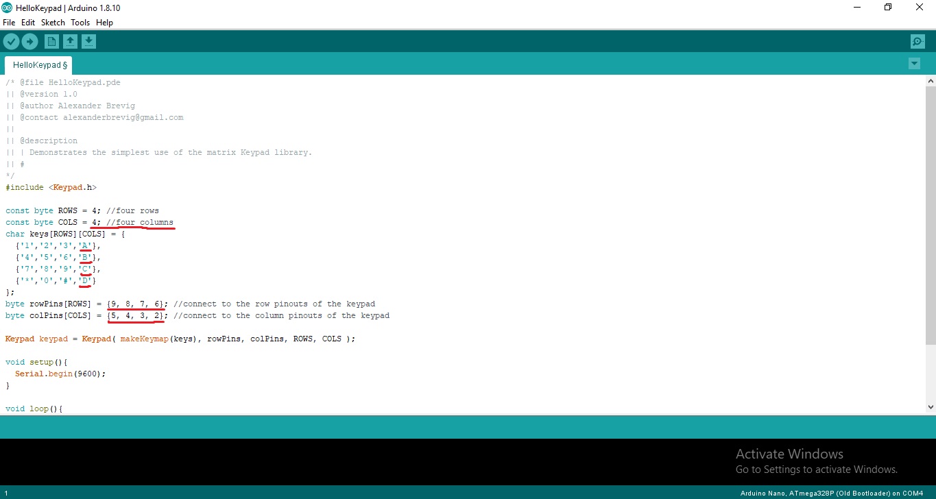
Before starting, check with your connections. For this you will be needing the 'HelloKeypad' sketch from the examples folder. You have to make some changes because this sketch is designed for the 4x3 matrix keypad. I have indicated the changes in the image below.
Now let's move on to the coding for this project. 

Keys and their functions

  • 1 - Turn on/off first RGB LED
  • 2 - Turn on/off second RGB LED
  • 3 - Turn on/off third RGB LED
  • A - Turn on/off Red pin
  • B - Turn on/off Green pin
  • C - Turn on/off Blue pin
  • 0 - Switch off all three LEDs
Let me explain you how this works. If I press '1' and press 'A', the first RGB LED will turn Red. If I press 'B' afterwards, the RGB LED will turn orange due to the combination of both Red and Green lights. If I press 'B' again, the Green LED will turn off. Watch the YouTube video in the last section of this page to see how this works. If you have any questions, please feel free to comment below.

Your sketch is going to have the same lines of code from the example sketch shown in the picture above, and you are going to program the required buttons of the keypad to debounce. Declare all the LED pins as OUTPUT within void setup( ) function, by using pinMode( ) function. As I am using common anode RGB LEDs, I've initially set the pins of the LEDs HIGH.

If anyone has any questions with the coding, please feel free to comment below or send me an email at arduinoprojectsbyr@gmail.com.

Final Look

If anyone has any questions, or suggestions, about this project, please feel free to comment below or send me an email at arduinoprojectsbyr@gmail.com.


Comments

Popular posts from this blog

51. Buzz wire game using Arduino

Hello everyone! This is my first Arduino project in 2020 and it is going to be a fun and simple project. You would have heard of the Buzz Wire, a steady hand game, and today you will be learning to make one using Arduino. Hardware components used in this project Arduino Nano USB Type A to mini B cable (for Arduino Nano) Solderless Breadboard - Mini and Full-size LEDs (x2) - Green and Red Resistors (x2) - 220 Ω  Active Buzzer module (KY-012) LCD display module with I2C interface - 16x2 Male-to-Male Jumper wires (x4) - 10cm Female-to-Male Jumper wires (x5) - 20 cm Jumpers (x5) - to reduce the usage of wires Copper wire  Tape (or any form of insulation)  Setup Your hardware setup must look somewhat similar to the ones in the images above. The beginning and end of the copper wire maze must be taped to prevent conductivity between the wire loop and maze. Connections LCD display module with I2C interface GND - Ground VCC - 5V SDA - A4 SCL - A5

71. Buzz Wire Game ( Version 2.0 ) using Arduino

Hey Everyone! I hope that everyone's safe during this pandemic. Today I am going to explain you about the second version of my Buzz wire game. People who are bored of staying indoors can find this game pretty interesting and fun to play.  If you are a beginner, you can start off with my first version of this project :  51. Buzz wire game using Arduino   Hardware components used in this project Arduino Uno Solderless Breadboard (x2) - Full/ Full+ LCD display module with I2C module - 16x2 Potentiometer - B20K Push-buttons (x3) Resistor - 220 Ω Active Buzzer module (KY-012) LED - Red Copper Wire - 19/ 20 gauge thick Male-to-Male Jumper wires - 10cm and 20cm Wire - Long enough to connect the loop of copper wire to ground Other tools required for this project Cutting pliers - To cut the right amount of copper wire Round-nose pliers - To bend the copper wire and make a maze and loop Hardware setup Connections Wire Maze - D2 Wire loop - Ground (GND) B20K Potentiometer S - A0 (+) - 5V (-)

86. RFID Health tag (Arduino and Python)

 Hey everyone, Sorry I have not uploaded in a while. Today, I will be sharing an interesting project with all of you. This RFID Health tag project is useful when it comes to keeping track of vaccinated individuals, their biodata and their health conditions and medications. For this project, you will be needing Arduino and Python. Read on further to see how I did this project. Hardware components used in this project Arduino Uno Solderless Breadboard - Half+ MRFC522 RFID reader RFID key tags (x5) Push-buttons (x2) Male-to-Male Jumper wires (x12) USB Type A/ B cable (for Arduino Uno) Software required Arduino IDE - latest version recommended Python 3.8 Schematic MFRC522 RFID reader SDA/ SS - D10 SCK - D13 MOSI - D11 MISO - D12 IRQ - Not connected GND - Ground RST/ RESET - D9 3.3V - 3.3V Push-buttons Submit button - D4 Retrieve button - D5 Coding Arduino For this project, you will be using the following libraries: MFRC522 by miguelbalboa -  https://github.com/miguelbalboa/rfid SPI - In-bu