
43. Arduino Radar

Hey everyone!
Today I will be teaching you about making an Arduino Radar. My Arduino Radar system is designed to detect objects within 40cm from the ultrasonic sensor. If an object is detected, the display will show the distance between the object and my ultrasonic sensor. Read on further to learn how I made my Arduino Radar system.

Supplies

  • Arduino Nano
  • USB Type A to mini B cable (for Arduino Nano)
  • Solderless Breadboard - Mini
  • Micro servo motor SG-90
  • Ultrasonic sensor (HC-SR04)
  • Cardboard bracket
  • Male-to-Male Jumper wires (x9) - 10cm 
  • 4-pin Female-to-Female Jumper wire (x1) - 70cm
  • Double sided tape

Setup


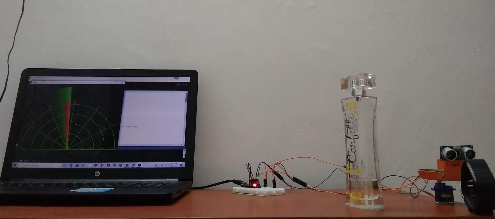
Your setup must look somewhat similar to that shown in the images above. Please watch my YouTube video posted in the last section of this post to learn more about the setup.

Connections

Micro Servo Motor (SG-90)

  • Red (+) - 5V
  • Brown (-) - Ground (GND)
  • Orange (S) - D9

Ultrasonic sensor (HC-SR04)

  • GND - Ground
  • Trig pin - D3
  • Echo pin - D4
  • Vcc - 5V

Coding

For this project, you will need to include the 'Servo' library by Michael Margolis in your sketch. If you are new to this library, and need reference to the functions, please feel free to follow the hyperlink in this section.
Create global variables for both trigger pin and echo pin using const int. Create a global variable to store the duration using the data type 'long', and another to store the distance measured using the data type 'int'. Create a servo object to control your servo motor.
Within void setup( ), use pinMode( ) to configure the trig pin and echo pin as OUTPUT and INPUT respectively. For this project, you will be using serial data transmission so set the data rate as 9600 bauds. Define the pin in which the servo motor is attached to, using the Servo.attach( ) function.
Within void loop( ), use for( ) function to rotate the servo motor from 15 to 165 degrees. Within for( ) function, use Servo.write( ) function, to set the position of the servo motor to the value. Set a delay period of 30 seconds, and use Serial.print( ) function to print the current degree and use a comma for indexing. Print your distance and a period for indexing.
You must repeat the previous lines using the for( ) function, so that the servo motor can move back to where it started - from 165 to 15 degrees.

How to measure distance:

Set the Trig pin on HIGH for 10 microseconds, after setting it LOW for 2 microseconds. Use pulseIn( ) function to read the echo pin while it is in HIGH state. The value returned by the pulseIn( ) function , in microseconds, must be stored in the duration variable. The value stored in the duration variable must be multiplied by the standard speed of sound in air and divided by 2. 

*Note: To get the Processing codes, please feel free to comment below or send me an email at arduinoprojectsbyr@gmail.com.

Final Look

If anyone has any questions, or suggestions, about this project, please feel free to comment below or send me an email at arduinoprojectsbyr@gmail.com.

Comments

Popular posts from this blog

51. Buzz wire game using Arduino

Hello everyone! This is my first Arduino project in 2020 and it is going to be a fun and simple project. You would have heard of the Buzz Wire, a steady hand game, and today you will be learning to make one using Arduino. Hardware components used in this project Arduino Nano USB Type A to mini B cable (for Arduino Nano) Solderless Breadboard - Mini and Full-size LEDs (x2) - Green and Red Resistors (x2) - 220 Ω  Active Buzzer module (KY-012) LCD display module with I2C interface - 16x2 Male-to-Male Jumper wires (x4) - 10cm Female-to-Male Jumper wires (x5) - 20 cm Jumpers (x5) - to reduce the usage of wires Copper wire  Tape (or any form of insulation)  Setup Your hardware setup must look somewhat similar to the ones in the images above. The beginning and end of the copper wire maze must be taped to prevent conductivity between the wire loop and maze. Connections LCD display module with I2C interface GND - Ground VCC - 5V SDA -...

70. Arduino Stopwatch and Timer

Hello everyone! Today I am going to explain you about making an Arduino Stopwatch and Timer, which can be used for time based projects. Read on further to learn more about this project. Hardware components used in this project Arduino Uno USB Type A/ B cable Solderless Breadboard - Full+ LCD display module with I2C interface - 16x2 Potentiometer - 10K Push-buttons (x5) Active Buzzer module (KY-012) LED - Red Resistors (x6) - 10kΩ (x5) and 220Ω (x1) Male-to-Male Jumper wires - 10cm and 20cm Jumpers - to reduce the usage of wires Hardware setup Connections 10K Potentiometer S - A0 (+) - 5V (-) - Ground (GND) Active Buzzer module S - D7 (+) - 5V (-) - Ground (GND) 16x2 LCD display module with I2C interface GND - Ground VCC - 5V SDA - A4 SCL - A5 Push-buttons (+) - 5V (-) - Ground (GND) S - D2, D3, D4, D5, D6 Coding Now, I will explain you about how this real-time project works and you can figure out the coding by this idea.  Push-buttons and their functions D2 - Set Countdown timer D3...

85. Analog and Digital Clock on Adafruit TFT Display using Arduino

 Hey everyone, Sorry I have not posted in a while. Today, I will be presenting you my Analog and Digital Clock on Adafruit TFT Display using Arduino. You can find the schematic and code explanation within this post. Read on further to learn how I did this project. Hardware components used in this project Arduino Mega 2560 Adafruit 2.8" TFT Touch Shield for Arduino w/ Capacitive Touch - You could also use any other Arduino compatible TFT display DS1307 RTC Module Solderless Breadboard - Half+ (This is optional if you are connecting the RTC module to the development board directly) Jumper wires (x4) - Male/Male jumper wires if using solderless breadboard. Female/Male if connecting RTC module directly to Arduino Mega. Software apps Arduino IDE - latest version is recommended Setup Connections DS1307 RTC Module SCL - A5 SDA - A4 VCC - 5V GND - Ground Adafruit TFT Touch shield You can simply place the Adafruit TFT Touch shield onto your Arduino Mega 2560 development board. Make sure to...