
24. RFID based Security System (Basic)

Hey guys!

Today we will be learning how to make a basic security system using Radio-frequency identification. RFID is one method of automatic identification and data capture, and is used in many industries. Let me give you a glimpse of this project. Initially, we will scan our tags with the MFRC522 RFID reader  module to record the data stored in them. RFID tags come in many forms, such as inlay, label, card, badge, hard tag and key tag, and in this project I will be using an RFID key tag and card tag. 
Then, we will upload the codes to start this project. In this project, the key tag will be the recognised user and the card tag will be the unidentified user.


How do RFID systems work?
RFID systems use radio waves to transmit information from the tag to the antenna connected to the reader. There are three different types of RFID systems:
  • Active
  • Passive
  • Semi- Passive/Active
The RFID system in this project is passive. To get a detailed explanation about the basic RFID systems, please visit: https://learn.sparkfun.com/tutorials/rfid-basics/all.

Supplies

  • Arduino Uno/Nano
  • Type A/B USB cable (for Arduino Uno) or Type A to mini B USB cable (for Arduino Nano)
  • Solderless Breadboard
  • MFRC522 RFID reader module
  • RFID tags - Card and Key tag
  • Active Buzzer Module (KY - 012)
  • LEDs (x2) - Green and Red
  • Resistors (x2) - 220Ω
  • Male-to-Male Jumper wires (x25) - 10cm
  • 3 pin Female-to-Female Jumper wires (x4) - 70cm
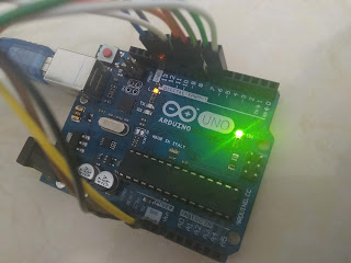
Setup

Your hardware setup must look somewhat similar to this. Please watch my YouTube video posted at the bottom of this page to learn more about this setup.

Connections

MFRC522 RFID reader module

  • RST/ RESET - D9
  • SDA/ SS - D10
  • MOSI - D11
  • MISO - D12
  • SCK - D13
  • GND - Ground
  • 3.3 V - 3.3 V

LEDs
  • Red - D6
  • Green - D8
  • Cathode (LEDs) - GND (Ground)
Buzzer
  • Signal - D7
  • (+) - 5V
  • (-) - GND (Ground)

Coding

You have to install the MFRC522 library in your Arduino IDE software. Go to Examples, open this library's folder, and open the sketch with the name 'DumpInfo'. Upload this sketch to your Arduino board and open the 'Serial Monitor'. Place your key tag in front of the MFRC522 RFID reader module and wait for a few seconds. You will see the data (which is stored in the tag) print on the Serial Monitor along with the UID (Unique Identification) tag. Write down the UID tag or store it for later uses.
Watch my YouTube video to get an idea about how this project works and try to work out the codes. If you need help, please feel free to comment below or send an email to arduinoprojectsbyr@gmail.com, and I will guide you.

Final Look

If anyone has any questions, or suggestions, about this project, please feel free to comment below, or send an email to arduinoprojectsbyr@gmail.com.


Comments

Popular posts from this blog

77. Controlling Micro servo Robotic Arm with MPU-6050 sensor module

 Hey everyone! I am back with an interesting project. Today, you will be learning about controlling a Simple 2 axis Robotic Arm, made from Micro servo motors, with an MPU-6050 sensor module. Please feel free to visit my previous blog post to learn about the MPU-6050 sensor module. Hardware components used in this project Arduino Mega 2560 - You could use any other Arduino microcontroller, but make sure you use an external power supply. USB Type A/B cable (for Arduino Mega 2560) MPU-6050 sensor module SG-90 Tower Pro Micro Servo motor (x2) Male-to-Male Jumper wires (x6) Male-to-Female Jumper wires (x5) Setup Schematic MPU-6050 sensor module VCC - 3.3V GND - Ground SDA - D20 (Arduino Mega 2560), A4 (Arduino Uno and Nano) SCL - D21 (Arduino Mega 2560), A5 (Arduino Uno and Nano) INT - D2 Micro servo motor (Roll) S (Yellow/ Orange) - D9 + (Red) - 5V - (Black/ Brown) - GND  Micro servo motor (Pitch) S (Yellow/ Orange) - D10 + (Red) - 5V - (Black/ Brown) - GND Coding As I alread...

57. Using Blynk with Arduino Uno and ESP8266 WiFi module

Hello Everyone! Today I am going to explain you how to connect your Arduino Uno with Blynk using the ESP8266 WiFi module. I have already demonstrated you about connecting your Arduino Uno with Blynk app using the Ethernet Shield W5100 and this will be the second version of that project .  Hardware components used in this project Arduino Uno ESP-01 ESP8266 WiFi module USB to TTL converter Solderless Breadboard - Half+ Breadboard power supply module - 3.3V/ 5V RGB LEDs (x3) - Common Anode Resistors (x3) - 220 Ω Relay module - 5V single channel Male-to-Male Jumper wires Female-to-Male Jumper wires Setup Your setup must look somewhat similar to that shown in the images above. Connections ESP8266 ESP-01 wifi module GND - Ground GPIO0- Not connected GPIO2 - Not connected RXD - D2 TXD - D3 CH_PD - VCC - 3.3V RESET - Not connected VCC - 3.3V  *Note: Do not connect your ESP8266 ESP-01 wifi module with 5V. RGB LED - Common Anode Anode -...

70. Arduino Stopwatch and Timer

Hello everyone! Today I am going to explain you about making an Arduino Stopwatch and Timer, which can be used for time based projects. Read on further to learn more about this project. Hardware components used in this project Arduino Uno USB Type A/ B cable Solderless Breadboard - Full+ LCD display module with I2C interface - 16x2 Potentiometer - 10K Push-buttons (x5) Active Buzzer module (KY-012) LED - Red Resistors (x6) - 10kΩ (x5) and 220Ω (x1) Male-to-Male Jumper wires - 10cm and 20cm Jumpers - to reduce the usage of wires Hardware setup Connections 10K Potentiometer S - A0 (+) - 5V (-) - Ground (GND) Active Buzzer module S - D7 (+) - 5V (-) - Ground (GND) 16x2 LCD display module with I2C interface GND - Ground VCC - 5V SDA - A4 SCL - A5 Push-buttons (+) - 5V (-) - Ground (GND) S - D2, D3, D4, D5, D6 Coding Now, I will explain you about how this real-time project works and you can figure out the coding by this idea.  Push-buttons and their functions D2 - Set Countdown timer D3...