
13. Alarm device using Mercury Tilt switch

Mercury Tilt switch alarm is really useful when it comes to security purposes as it enables the easy detection of orientation or inclination. Examples include:
  • Used in vehicles so that it alerts others when the vehicle gets jacked up, for stealing wheels and towing.
  • Can be used in valuable items in places like museums, so that the alarm is triggered when it is lifted.
In this project, the Arduino Uno R3 will be programmed in such a way that a buzzer and red LED will light up when there is a change in orientation, and a green LED will light up when the mercury tilt switch is in correct position.

So how does a mercury tilt switch work?
The switch is positioned with respect to gravity forces so that the mercury moves away from the contacts so that the switch is open. When there is an inclination or any slight differences in its orientation, the mercury ball rolls in the tube touching both contacts and closing the switch.

Supplies:

  • LED - Red and Green
  • Resistor - 220 Ω (x2)
  • Mercury Tilt switch

  • Buzzer - Active
  • Arduino Uno R3
  • Solderless Breadboard - Mini
  • Jumper Wires - Male-to-Male [10 cm] (x13) | Male-to-Female [20 cm] (x3)

  • Jumper cables - Female-to-Female [70cm] (x3)
  • 9V battery
  • 9V Battery connector

Setting up your hardware
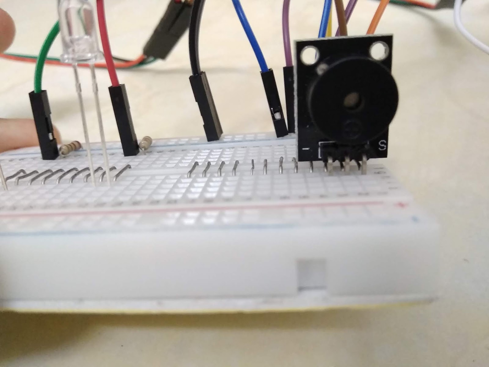


Connections:

  • Mercury Tilt switch - D3
  • Cathode (LED) - Ground (GND)
  • Anode (Red) - D6
  • Anode (Green) - D5
  • Buzzer - D4

Coding

Final Look

Comments

Popular posts from this blog

85. Analog and Digital Clock on Adafruit TFT Display using Arduino

 Hey everyone, Sorry I have not posted in a while. Today, I will be presenting you my Analog and Digital Clock on Adafruit TFT Display using Arduino. You can find the schematic and code explanation within this post. Read on further to learn how I did this project. Hardware components used in this project Arduino Mega 2560 Adafruit 2.8" TFT Touch Shield for Arduino w/ Capacitive Touch - You could also use any other Arduino compatible TFT display DS1307 RTC Module Solderless Breadboard - Half+ (This is optional if you are connecting the RTC module to the development board directly) Jumper wires (x4) - Male/Male jumper wires if using solderless breadboard. Female/Male if connecting RTC module directly to Arduino Mega. Software apps Arduino IDE - latest version is recommended Setup Connections DS1307 RTC Module SCL - A5 SDA - A4 VCC - 5V GND - Ground Adafruit TFT Touch shield You can simply place the Adafruit TFT Touch shield onto your Arduino Mega 2560 development board. Make sure to...

77. Controlling Micro servo Robotic Arm with MPU-6050 sensor module

 Hey everyone! I am back with an interesting project. Today, you will be learning about controlling a Simple 2 axis Robotic Arm, made from Micro servo motors, with an MPU-6050 sensor module. Please feel free to visit my previous blog post to learn about the MPU-6050 sensor module. Hardware components used in this project Arduino Mega 2560 - You could use any other Arduino microcontroller, but make sure you use an external power supply. USB Type A/B cable (for Arduino Mega 2560) MPU-6050 sensor module SG-90 Tower Pro Micro Servo motor (x2) Male-to-Male Jumper wires (x6) Male-to-Female Jumper wires (x5) Setup Schematic MPU-6050 sensor module VCC - 3.3V GND - Ground SDA - D20 (Arduino Mega 2560), A4 (Arduino Uno and Nano) SCL - D21 (Arduino Mega 2560), A5 (Arduino Uno and Nano) INT - D2 Micro servo motor (Roll) S (Yellow/ Orange) - D9 + (Red) - 5V - (Black/ Brown) - GND  Micro servo motor (Pitch) S (Yellow/ Orange) - D10 + (Red) - 5V - (Black/ Brown) - GND Coding As I alread...

70. Arduino Stopwatch and Timer

Hello everyone! Today I am going to explain you about making an Arduino Stopwatch and Timer, which can be used for time based projects. Read on further to learn more about this project. Hardware components used in this project Arduino Uno USB Type A/ B cable Solderless Breadboard - Full+ LCD display module with I2C interface - 16x2 Potentiometer - 10K Push-buttons (x5) Active Buzzer module (KY-012) LED - Red Resistors (x6) - 10kΩ (x5) and 220Ω (x1) Male-to-Male Jumper wires - 10cm and 20cm Jumpers - to reduce the usage of wires Hardware setup Connections 10K Potentiometer S - A0 (+) - 5V (-) - Ground (GND) Active Buzzer module S - D7 (+) - 5V (-) - Ground (GND) 16x2 LCD display module with I2C interface GND - Ground VCC - 5V SDA - A4 SCL - A5 Push-buttons (+) - 5V (-) - Ground (GND) S - D2, D3, D4, D5, D6 Coding Now, I will explain you about how this real-time project works and you can figure out the coding by this idea.  Push-buttons and their functions D2 - Set Countdown timer D3...