
08. Using a potentiometer to control the blink rate of an LED

The supplies and hardware setup is exactly that of the previous project. In this project, we will see how the potentiometer affects the blink rate of an LED.

Supplies

  • LED
  • Resistor - 220Ω
  • Potentiometer


  • Arduino Uno R3
  • Solderless Breadboard - Mini

Setting up your hardware
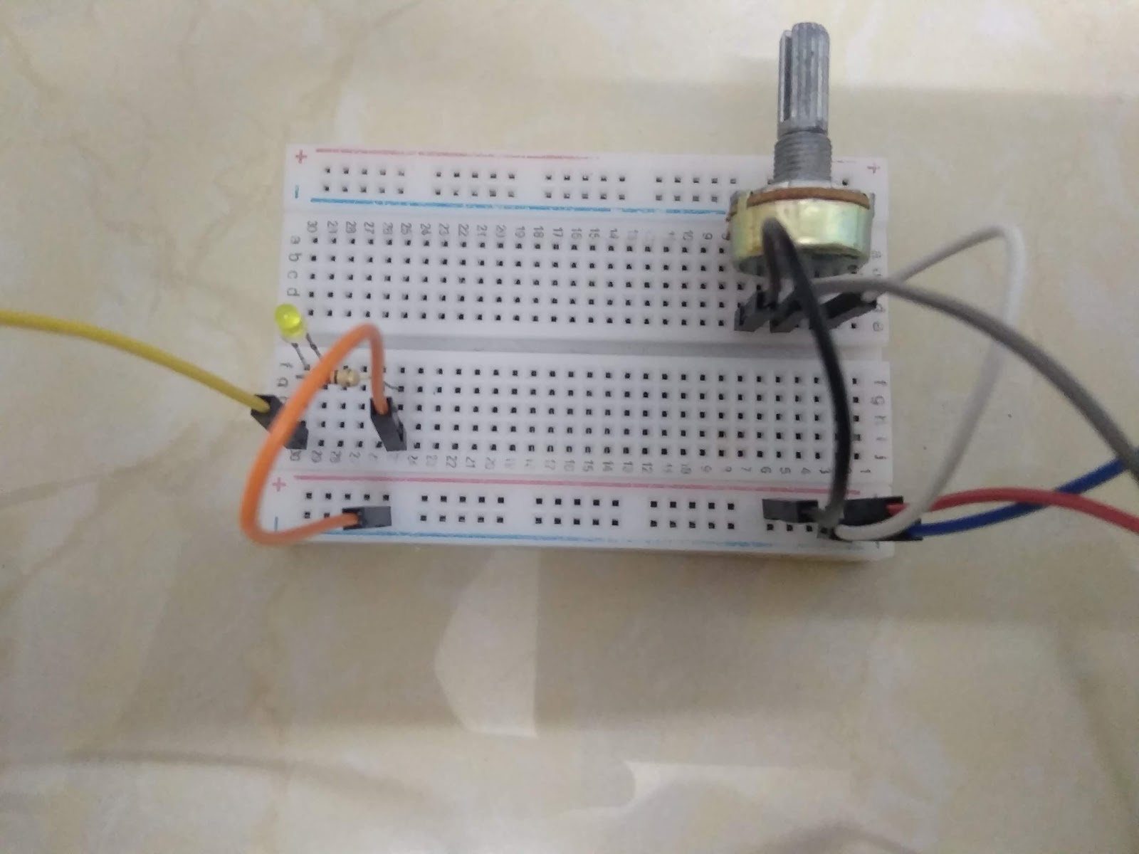


Connections

  • Cathode (LED) ---> Ground (GND)
  • Anode (LED) ---> D9
  • Middle pin of potentiometer ---> A0

Coding

Final Look


Comments

Popular posts from this blog

51. Buzz wire game using Arduino

Hello everyone! This is my first Arduino project in 2020 and it is going to be a fun and simple project. You would have heard of the Buzz Wire, a steady hand game, and today you will be learning to make one using Arduino. Hardware components used in this project Arduino Nano USB Type A to mini B cable (for Arduino Nano) Solderless Breadboard - Mini and Full-size LEDs (x2) - Green and Red Resistors (x2) - 220 Ω  Active Buzzer module (KY-012) LCD display module with I2C interface - 16x2 Male-to-Male Jumper wires (x4) - 10cm Female-to-Male Jumper wires (x5) - 20 cm Jumpers (x5) - to reduce the usage of wires Copper wire  Tape (or any form of insulation)  Setup Your hardware setup must look somewhat similar to the ones in the images above. The beginning and end of the copper wire maze must be taped to prevent conductivity between the wire loop and maze. Connections LCD display module with I2C interface GND - Ground VCC - 5V SDA -...

70. Arduino Stopwatch and Timer

Hello everyone! Today I am going to explain you about making an Arduino Stopwatch and Timer, which can be used for time based projects. Read on further to learn more about this project. Hardware components used in this project Arduino Uno USB Type A/ B cable Solderless Breadboard - Full+ LCD display module with I2C interface - 16x2 Potentiometer - 10K Push-buttons (x5) Active Buzzer module (KY-012) LED - Red Resistors (x6) - 10kΩ (x5) and 220Ω (x1) Male-to-Male Jumper wires - 10cm and 20cm Jumpers - to reduce the usage of wires Hardware setup Connections 10K Potentiometer S - A0 (+) - 5V (-) - Ground (GND) Active Buzzer module S - D7 (+) - 5V (-) - Ground (GND) 16x2 LCD display module with I2C interface GND - Ground VCC - 5V SDA - A4 SCL - A5 Push-buttons (+) - 5V (-) - Ground (GND) S - D2, D3, D4, D5, D6 Coding Now, I will explain you about how this real-time project works and you can figure out the coding by this idea.  Push-buttons and their functions D2 - Set Countdown timer D3...

62. Controlling VLC Media Player with an IR remote - Using Arduino and Python

Hello Everyone! In my previous project, I have explained you about controlling the VLC media player by your hands and in this version, I will be using my own IR remote to execute more functions. In my previous version, I only presented three functions which were Play/ Pause, Volume up and Volume down, but in this version I will be presenting eight more functions. Read on further to learn more about this project. You will also find this blog post as a helpful guide to make your DIY IR remote. Hardware components used in this project IR remote Arduino Uno USB Type A/ B cable (for Arduino Uno) Solderless Breadboard - Full+ IR transmitter module (KY-005) Push-button (x11) Male-to-Male Jumper wires (x13) - 20cm Jumpers (x12) - To reduce the usage of wires IR receiver Arduino Nano USB Type A to mini B cable (for Arduino Nano) Solderless Breadboard - Half+ IR receiver module (KY-022) Male-to-Male Jumper wires (x3) - 10cm Setup Your setup must look some...